Electromagnetism
When a conductor carrying a current is placed in a magnetic field, it experiences a magnetic force.
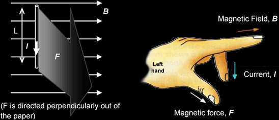
The figure above shows a wire of length L carrying a current I and lying in a magnetic field of flux density B. Suppose the angle between the current I and the field B is θ , the magnitude of the force F on the conductor is given by
F = BILsinθ
The direction of the force can be found using Fleming‟s Left Hand Rule (see figure above). Note that the force is always perpendicular to the plane containing both the current I and the magnetic field B.
- If the wire is parallel to the field lines, then θ = 0°, and F = 0. (No magnetic force acts on the wire)
- If the wire is at right angles to the field lines, then θ = 90°, and the magnetic force acting on the wire
would be
maximum (F = BIL)
Example
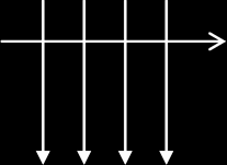
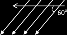
The 3 diagrams below each show a magnetic field of flux density 2 T that lies in the plane of the page. In
each case, a current I of 10 A is directed as shown. Use Fleming's Left Hand Rule to predict the directions
of the forces and work out the magnitude of the forces on a 0.5 m length of wire that carries the current.
(Assume the horizontal is the current)
 |
 |
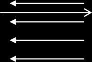 |
| F = BIL sinθ = 2 x 10 x 0.5 x sin90 = 10 N | F = BIL sinθ = 2 x 10 x 0.5 x sin60 = 8.66 N | F = BIL sin θ = 2 x 10 x 0.5 x sin180 = 0 N |
Magnetic flux density B is defined as the force acting per unit current in a wire of unit length at right-angles to the field
B = F / ILsin θ → F = B I L sin θ {θ: Angle between the B and L}
{NB: write down the above defining equation & define each symbol if you're not able to give the “statement form”.}
Direction of the magnetic force is always perpendicular to the plane containing the current I and B {even if θ ≠ 0}
The Tesla is defined as the magnetic flux density of a magnetic field that causes a force of one newton to act on a current of one ampere in a wire of length one metre which is perpendicular to the magnetic field.
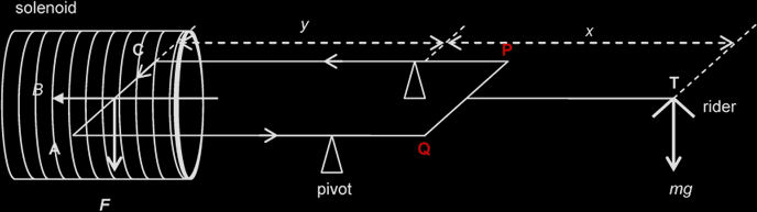
By the Principle of moments, Clockwise moments = Anticlockwise moments
mg ∙ x = F ∙ y
= BILsin90 ∙ y
B = mgx / ILy
Example
A 100-turn rectangular coil 6.0 cm by 4.0 cm is pivoted about a horizontal axis as shown below. A horizontal uniform magnetic field of direction perpendicular to the axis of the coil passes through the coil.
Initially, no mass is placed on the pan and the arm is kept horizontal by adjusting the counter-weight. When a current of 0.50 A flows through the coil, equilibrium is restored by placing a 50 mg mass on the pan, 8.0 cm from the pivot. Determine the magnitude of the magnetic flux density and the direction of the current in the coil.
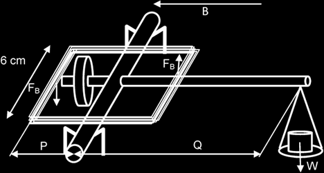
Taking moments about the pivot, sum of Anti-clockwise moments = Clockwise moment
(2 x n)(FB) x P = W x Q
(2 x n)(B I L) x P = m g x Q, where n: no. of wires on each side of the coil
(2 x 100)(B x 0.5 x 0.06) x 0.02 = 50 x 10-6 x 9.81 x 0.08
B = 3.27 x 10⁻⁴ T
Force acting on a moving charge: F = B Q v sin θ {θ: Angle between B and v.}
The direction of this force may be found by using Fleming's left hand rule.
The angle θ determines the type of path the charged particle will take when moving through a uniform magnetic field:
- If θ = 0°, the charged particle takes a straight path since it is not deflected (F = 0)
- If θ = 90°, the charged particle takes a circular path since the force at every point in the path is perpendicular to the motion of the charged particle.
Since F is always be perpendicular to v {even if θ ≠0},
the magnetic force can provide the centripetal force, → Bqv = mv2 / r
Example:
An electron moves in a circular path in vacuum under the influence of a magnetic field.
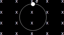
The radius of the path is 0.010 m and the flux density is 0.010 T. Given that the mass of the electron is 9.11 x 10⁻³¹ kg and the charge on the electron is -1.6 x 10⁻¹⁹ C, determine
(i) whether the motion is clockwise or anticlockwise:
The magnetic force on the electron points towards the centre of the circular path; hence using Fleming's left hand rule, we deduce that the current I points to the left. The electron must be moving clockwise.(ii) the velocity of the electron:
Bqv = mv2 / r
v = Bqr / m = [(0.010)(1.6 x 10⁻¹⁹)(0.010)] / 9.11 x 10-31 = 1.76 x 10⁷ ms-1
Crossed-Fields in Velocity Selector:
A setup whereby an E-field and a B-field are perpendicular to each other such that they exert equal & opposite forces on a moving charge {if the velocity is “a certain value”}
Magnetic Force = Electric Force
B q v = q E
v = E / B
- Only particles with speed = E / B emerge from the cross-fields undeflected.
- For particles with speed > E / B, Magnetic Force > Electric Force
- For particles with speed < E / B, Magnetic Force < Electric Force
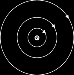
Sketching flux patterns:
| LONG STRAIGHT WIRE (Field goes out of the paper) |
LONG STRAIGHT WIRE (Field goes into the paper) |
 |
 |
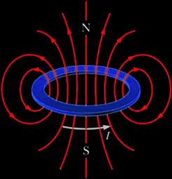
| FLAT CIRCULAR COIL | SOLENOID |
 |
 |
The strength of the generated magnetic field can be increased (by about 1000 times) by adding a ferrous (iron) core inside the solenoid. This is because a ferrous material has a higher permeability than air. Another explanation is that iron, being a ferromagnetic material, becomes magnetised when placed into the solenoid, thus contributing to the overall magnetic field strength of the solenoid.
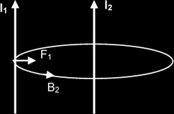
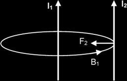
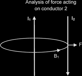
Each conductor should thus experience a force (F = BIL sinθ), either of attraction or repulsion, depending on the direction of the currents. Whether the forces are attractive or repulsive can be predicted using the Right hand grip rule and Fleming‟s left-hand rule.
| CURRENTS FLOWING IN SAME DIRECTION | |
 |
 |
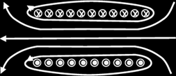
| CURRENTS FLOWING IN OPPOSITE DIRECTIONS | |
 |
|
Example:
A long length of aluminium foil ABC is hung over a wooden rod as shown below. A large current is momentarily passed through the foil in the direction ABC, and the foil moves.
(i) Draw arrows to indicate the directions in which AB and BC move
Since currents in AB and BC are 'unlike' currents (they are flowing in opposite directions), the two foil sections AB and BC will repel each other.(ii) Explain why the foil moves in this way
The current in the left foil AB produces a magnetic field in the other (BC). According to the Right Hand Grip Rule & Fleming‟s Left Hand Rule, the force on BC is away from and perpendicular to AB. By a similar consideration, the force on AB is also away from BC. Thus the forces between the foils are repulsive.