D.C. Circuits
Circuit Symbols:
Open Switch |
Closed Switch |
Lamp |
Cell |
Battery |
Voltmeter |
 Resistor |
 Fuse |
 Ammeter |
 Variable resistor |
 Thermistor |
 Light dependent resistor (LDR) |
Resistors in Series: R = R1 + R2 + ...
Resistors in Parallel: 1/R = 1/R1 + 1/R2 + …
Example 1:
Three resistors of resistance 2 Ω, 3 Ω and 4 Ω respectively are used to make the combinations X, Y and Z shown in the diagrams. List the combinations in order of increasing resistance.

Resistance for X = [1/2 + 1/(4+3)]-1 = 1.56 Ω
Resistance for Y = 2 + (1/4 + 1/3)-1 = 3.71 Ω
Resistance for Z = (1/3 + 1/2 + 1/4)-1 = 0.923 Ω
Therefore, the combination of resistors in order of increasing resistance is Z X Y.
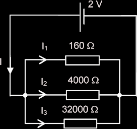
Example:
|
 |
Example:
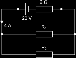
A battery with an EMF of 20 V and an internal resistance of 2.0 Ω is connected to resistors R1 and R2 as shown in the diagram. A total current of 4.0 A is supplied by the battery and R2 has a resistance of 12 Ω. Calculate the resistance of R1 and the power supplied to each circuit component.
|
 |
For potential divider with 2 resistors in series,
Potential drop across R1, V1 = R1 / (R1 + R2) x PD across R1 & R2
Potential drop across R2, V1 = R2 / (R1 + R2) x PD across R1 & R2
Example:
Two resistors, of resistance 300 kΩ and 500 kΩ respectively, form a potential divider with outer junctions maintained at potentials of +3 V and -15 V.

Determine the potential at the junction X between the resistors.
The potential difference across the 300 kΩ resistor = 300 / (300 + 500) [3 - (-15)] = 6.75 V
The potential at X = 3 - 6.75 = -3.75 V
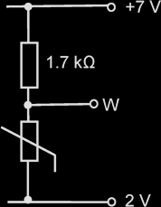
A thermistor is a resistor whose resistance varies greatly with temperature. Its resistance decreases with increasing temperature. It can be used in potential divider circuits to monitor and control temperatures. Example:
|
 |
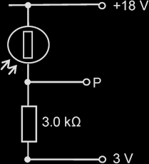
A Light dependent resistor (LDR) is a resistor whose resistance varies with the intensity of light falling on it. Its resistance decreases with increasing light intensity. It can be used in a potential divider circuit to monitor light intensity. Example:
|
 |
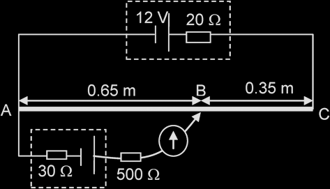
The potential difference along the wire is proportional to the length of the wire. The sliding contact will move along wire AB until it finds a point along the wire such that the galvanometer shows a zero reading.
When the galvanometer shows a zero reading, the current through the galvanometer (and the device that is being tested) is zero and the potentiometer is said to be “balanced”.
If the cell has negligible internal resistance, and if the potentiometer is balanced,
EMF / PD of the unknown source, V = [L1 / (L1 + L2)] x E
Example:
|
 |