Alternating Currents
Characteristics of alternating currents
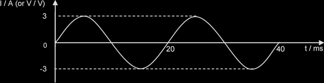
Peak current, I0 = 3 A
Peak-to-peak current, Ip-p = 6 A
Period, T = 20 ms
Frequency, f = 1 / T = 50 Hz
Angular Frequency, ω = 2 π f = 314 rad s-1
Instantaneous current: the current at a particular instant.
- Since this A.C. signal can be described by the equation:
- I = I0 sin (ω t)
or V = V0 sin (ω t)
the instantaneous current I or voltage V at time t is given by I0 sin (ωt) or V0 sin (ωt).
Note: Both the period and amplitude of a sinusoidal A.C should be constant.
Root-mean-square current of an alternating current is defined as that steady {NOT direct} current that produces the same heating effect {ie I2 R} as the alternating current in a given resistor.
(Instantaneous) sinusoidal current: I = I0sinωt , { Similarly, V = V0 sinωt }
Irms = Io / √2, Vrms = vo / √2, {for sinusoidal ac only}
Relationship between Peak, & RMS values of PD & Current: V0 = I0R , Vrms = IrmsR
Mean/Ave Power, Pave = Irms2 R = Vrms2 / R = Irms / Vrms = ½ x Maximum Instantaneous Power = ½ I0V0 {for sinusoidal AC}
Max (Instantaneous) Power, Pmax = I0V0 = I02 R
The root-mean-square (R.M.S.) value, Irms, of an A.C. is the magnitude of the direct current that produces the same average heating effect as the alternating current in a given resistance whereas peak value is the maximum current of an AC.
Ideal transformer: Vp Ip = Vs Is → NS / NP = VS / VP = IP / IS
{Mean power in the primary coil = Mean power in the secondary coil )
{Values of I & V may be either R.M.S. or peak but not instantaneous values; NS / NP: turns ratio}
Power Loss during Transmission of Electrical Power
![]()
Power Generated at power station Pgen = Vi I,
where I: current in the transmission, Vi: Voltage at which power is transmitted
I = Pgen / Vi
Power Loss in Transmission Cables, PL = I2 RC = (Pgen / Vi)2 RC ;RC = cable resistance
Thus to reduce power loss, for a given amt of power generated, electricity is transmitted at high voltage Vi {ie low current}. {Vi is NOT the pd across the cables}
Rectification with a diode
If a single diode is connected to an A.C. circuit as shown, a half-wave rectification occurs.
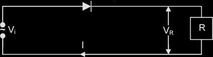
The graphs for the input and output voltages, and the output current, are shown below.
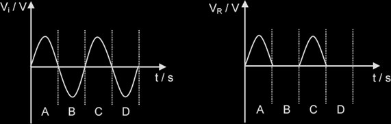
In the regions A and C, the diode is forward biased, allowing current to flow. When the input voltage becomes negative, the diode prevents the current flow, because it is reverse biased.