FRACTIONAL DISTILLATION OF IDEAL MIXTURES OF LIQUIDSThis page explains how the fractional distillation (both in the lab and industrially) of an ideal mixture of liquids relates to their phase diagram. This is the second page in a sequence of three pages. |
|
|
Important: If you have come straight to this page from a search engine and are looking for simple factual information about fractional distillation, this is probably not the page for you! It deals with the theory behind fractional distillation. Again, if you have come straight to this page, you won't make much sense of it unless you first read the page about phase diagrams for ideal mixtures. You will find a link at the bottom of that page which will bring you back here again. |
|
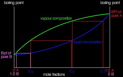
Using the phase diagramOn the last page, we looked at how the phase diagram for an ideal mixture of two liquids was built up. I want to start by looking again at material from the last part of that page. The next diagram is new - a modified version of diagrams from the previous page.
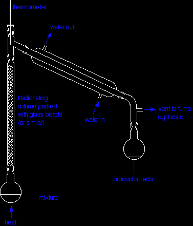
If you boil a liquid mixture C1, you will get a vapour with composition C2, which you can condense to give a liquid of that same composition (the pale blue lines). If you reboil that liquid C2, it will give a vapour with composition C3. Again you can condense that to give a liquid of the same new composition (the red lines). Reboiling the liquid C3 will give a vapour still richer in the more volatile component B (the green lines). You can see that if you were to do this once or twice more, you would be able to collect a liquid which was virtually pure B. The secret of getting the more volatile component from a mixture of liquids is obviously to do a succession of boiling-condensing-reboiling operations. It isn't quite so obvious how you get a sample of pure A out of this. That will become clearer in a while. Fractional distillation in the labThe apparatus A typical lab fractional distillation would look like this:
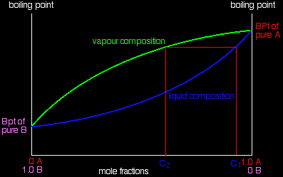
Some notes on the apparatus The fractionating column is packed with glass beads (or something similar) to give the maximum possible surface area for vapour to condense on. You will see why this is important in a minute. Some fractionating columns have spikes of glass sticking out from the sides which serve the same purpose. If you sketch this, make sure that you don't completely seal the apparatus. There has to be a vent in the system otherwise the pressure build-up when you heat it will blow the apparatus apart. In some cases, where you are collecting a liquid with a very low boiling point, you may need to surround the collecting flask with a beaker of cold water or ice. The mixture is heated at such a rate that the thermometer is at the temperature of the boiling point of the more volatile component. Notice that the thermometer bulb is placed exactly at the outlet from the fractionating column. Relating what happens in the fractionating column to the phase diagram Suppose you boil a mixture with composition C1. The vapour over the top of the boiling liquid will be richer in the more volatile component, and will have the composition C2.
That vapour now starts to travel up the fractionating column. Eventually it will reach a height in the column where the temperature is low enough that it will condense to give a liquid. The composition of that liquid will, of course, still be C2. |
|
|
Note: As you will see shortly, that is an oversimplification because "our" vapour will become mixed with other vapours generated by various other reboilings happening in the column. I can't see any way around this simplification! |
|
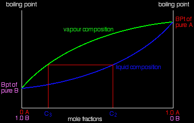
So what happens to that liquid now? It will start to trickle down the column where it will meet new hot vapour rising. That will cause the already condensed vapour to reboil.
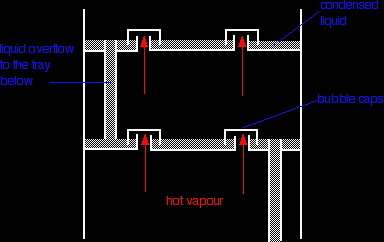
Some of the liquid of composition C2 will boil to give a vapour of composition C3. Let's concentrate first on that new vapour and think about the unvaporised part of the liquid afterwards. The vapour This new vapour will again move further up the fractionating column until it gets to a temperature where it can condense. Then the whole process repeats itself. Each time the vapour condenses to a liquid, this liquid will start to trickle back down the column where it will be reboiled by up-coming hot vapour. Each time this happens the new vapour will be richer in the more volatile component. The aim is to balance the temperature of the column so that by the time vapour reaches the top after huge numbers of condensing and reboiling operations, it consists only of the more volatile component - in this case, B. Whether or not this is possible depends on the difference between the boiling points of the two liquids. The closer they are together, the longer the column has to be. The liquid So what about the liquid left behind at each reboiling? Obviously, if the vapour is richer in the more volatile component, the liquid left behind must be getting richer in the other one. As the condensed liquid trickles down the column constantly being reboiled by up-coming vapour, each reboiling makes it richer and richer in the less volatile component - in this case, A. By the time the liquid drips back into the flask, it will be very rich in A indeed. So, over time, as B passes out of the top of the column into the condenser, the liquid in the flask will become richer in A. If you are very, very careful over temperature control, eventually you will have separated the mixture into B in the collecting flask and A in the original flask. Finally, what is the point of the packing in the column? To make the boiling-condensing-reboiling process as effective as possible, it has to happen over and over again. By having a lot of surface area inside the column, you aim to have the maximum possible contact between the liquid trickling down and the hot vapour rising. If you didn't have the packing, the liquid would all be on the sides of the condenser, while most of the vapour would be going up the middle and never come into contact with it. Fractional distillation industriallyThere is no difference whatsoever in the theory involved. All that is different is what the fractionating column looks like. The diagram shows a simplified cross-section through a small part of a typical column.
The column contains a number of trays that the liquid collects on as the vapour condenses. The up-coming hot vapour is forced through the liquid on the trays by passing through a number of bubble caps. This produces the maximum possible contact between the vapour and liquid. This all makes the boiling-condensing-reboiling process as efficient as possible. The overflow pipes are simply a controlled way of letting liquid trickle down the column. If you have a mixture of lots of liquids to separate (such as in petroleum fractionation), it is possible to tap off the liquids from some of the trays rather than just collecting what comes out of the top of the column. That leads to simpler mixtures such as gasoline, kerosene and so on. |
|
|
Note: At the moment, I don't have any intention to write specifically about petroleum (crude oil) distillation. If you do a Google search, you will already find far more than you could possibly read if you spent the whole of the next week at it! |
|
|
Where would you like to go now? Continue to the page about non-ideal liquid mixtures . . . To the phase equilibrium menu . . . To the Physical Chemistry menu . . .
|
|
